Where the cannon is used
The same cannon module is meant to drop into several instruments.
- Chime chandelier, turret layout. One cannon on a two-axis pan and tilt head (two NEMA 17 steppers on belts, after OpenTurret). Aims at stored presets, one per target.
- Chime chandelier, ring layout. One cannon in the middle of a circle of hanging tubes, spinning to face each one. Pan only, because the tube bottoms hang level. A slip ring passes power through the rotation.
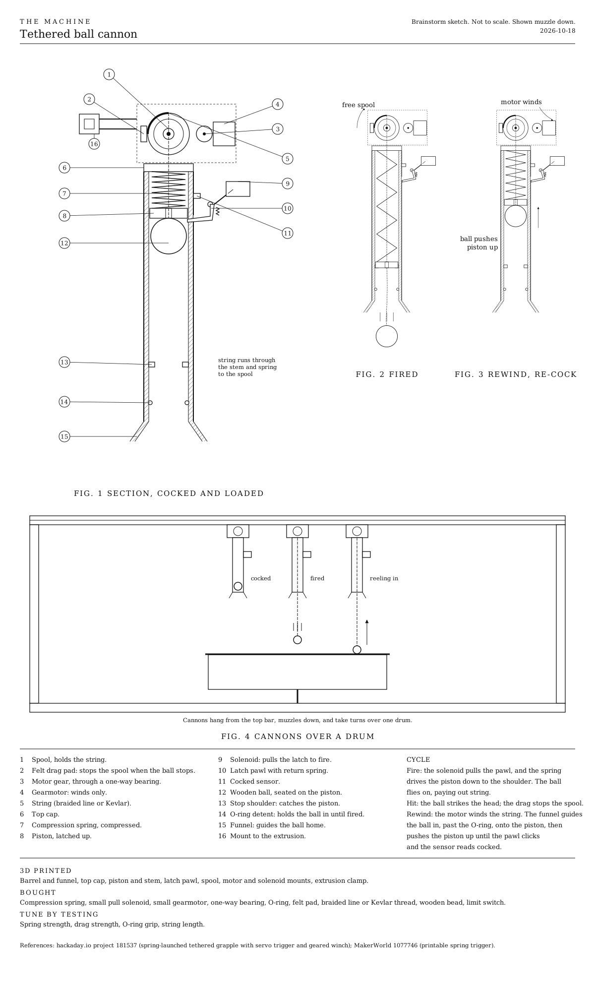
- Chime carousel. Four fixed cannons on drop rods from the midpoints of the frame’s top edges. The ring of chimes turns; the cannons stay still.
In all of them, the cannon fires level or slightly down, never upward.
Requirements
- Fires a tethered wooden ball hard enough to ring a hanging chime tube clearly, at a range of roughly 0.3 to 0.8 m.
- Fires on command with a short, repeatable delay, so it can be scheduled to land on a beat.
- Brings the ball back, re-cocks, and is ready again without any human touch.
- Fails safe: never fires from an unknown state, stops and holds on any fault.
- Runs on the shared power-tool battery. Mounts to aluminum extrusion.
- Mostly 3D printed, with a few bought parts (spring, solenoid, gearmotor, one-way bearing, sensors).
Changes for level firing
The first sketch fired downward, where gravity kept the ball seated and helped it fall back into the funnel. Firing level needs three changes.
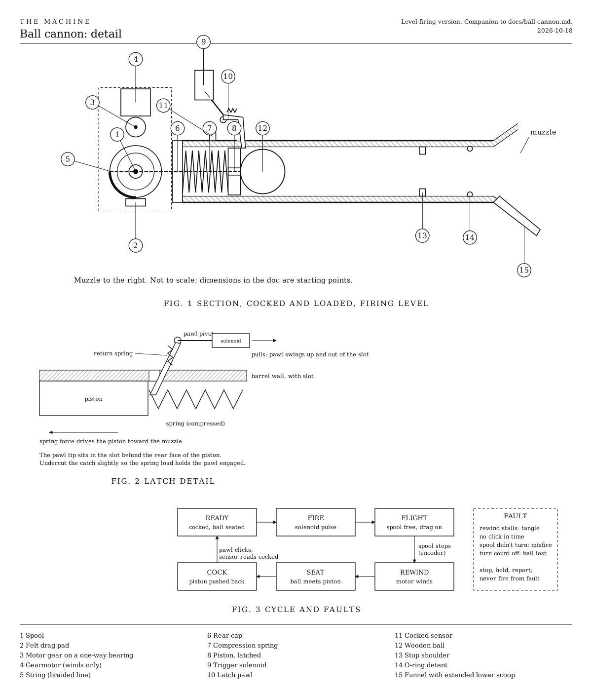
- The O-ring detent holds the ball. A soft O-ring in a groove near the muzzle pinches the ball lightly so it can’t roll out before firing. The shot pushes through it easily; the rewind pulls the ball back through it.
- The funnel gets a scoop lip. On a level shot, a returning ball swings low under the string. An extended lower lip on the funnel catches it and guides it back into the bore.
- Aim level or slightly down. A few degrees down helps the return: the ball hangs below the string’s line and lands on the scoop. Aiming upward fails, because the returning ball arrives from below the funnel and misses.
Mechanism
Numbers match the callouts on the detail drawing.
| # | Part | Notes |
|---|---|---|
| 1 | Spool | Holds the tether. About 12 mm winding radius. |
| 2 | Felt drag pad | Light friction on the spool so it stops when the ball stops and doesn’t overrun into a bird’s nest. |
| 3 | Motor gear on a one-way bearing | Drives the spool to wind. Freewheels when the ball pulls string out, so firing never back-drives the motor. |
| 4 | Gearmotor | Winds only. Small N20-size motor (see estimates). |
| 5 | String | Braided line (fishing line or trimmer-style). Runs from the ball, through the piston and spring, out the rear cap to the spool. |
| 6 | Rear cap | Closes the tube, holds the spring’s back end, has a smooth hole for the string. |
| 7 | Compression spring | The energy store. |
| 8 | Piston | Hollow, with a string hole through its center. A shoulder on the rear face catches the pawl. |
| 9 | Trigger solenoid | A small pull solenoid. Only lifts the pawl; it never pushes the ball. |
| 10 | Latch pawl | Pivoted lever with a return spring. Drops into a slot in the barrel wall behind the piston. |
| 11 | Cocked sensor | Microswitch or hall sensor that reads the pawl engaged. |
| 12 | Wooden ball | About 25 mm, drilled through for the tether, knotted at the front. |
| 13 | Stop shoulder | Catches the piston at the end of its stroke so it stays in the tube. |
| 14 | O-ring detent | Holds the ball in the bore until fired. |
| 15 | Funnel with scoop lip | Guides the returning ball into the bore. |
How a shot works
- Ready. The piston is pulled back against the spring and held by the pawl. The ball sits in front of the piston, held by the O-ring.
- Fire. The solenoid pulses and lifts the pawl. The spring drives the piston forward, the piston hits the ball, and the stop shoulder catches the piston. The ball flies out trailing string.
- Flight. The spool spins freely on the one-way bearing as string pays out. The felt drag stops the spool when the ball stops, so there’s no loose coil.
- Strike. The ball hits the chime and falls away, hanging on the tether.
- Rewind. The motor winds the spool. The ball swings back, the scoop lip catches it, and it is pulled through the funnel and the O-ring.
- Seat. The ball meets the front of the piston.
- Cock. The motor keeps winding. The ball pushes the piston back, compressing the spring, until the pawl drops into the slot with a click. The cocked sensor confirms and the motor stops.
The rewind and the click are audible and are part of the instrument’s sound.
Latch detail
The pawl’s tip sits in a slot in the barrel wall, just behind the piston’s rear face. The spring pushes the piston forward against the pawl, so the latch is loaded the whole time it’s cocked.
- Undercut the catch face slightly so the spring load pulls the pawl deeper into the slot rather than pushing it out. Without that, vibration or a knock could fire it.
- The pawl’s return spring presses it down onto the piston as the piston slides back, so it drops into the slot on its own at the end of the cocking stroke.
- The solenoid only has to overcome the return spring and the friction of the loaded catch. Keep the catch face smooth (a printed part with a small metal pin or a steel insert at the contact point) so the trigger force stays low and consistent.
Starting estimates
Rough numbers to size the first prototype. All of them need checking on the bench.
| Quantity | Estimate | Basis |
|---|---|---|
| Ball | 25 mm wooden, about 5 g | Craft bead |
| Muzzle speed | About 4 m/s | Enough to ring a chime at short range |
| Ball energy | About 0.04 J | ½ × 0.005 kg × (4 m/s)² |
| Spring energy needed | About 0.08 J | Assuming about 50% of the spring’s energy reaches the ball |
| Spring travel | 30 mm | Fits a short tube |
| Spring rate | About 180 N/m | From ½ k x² = 0.08 J at x = 0.03 m |
| Peak spring force | About 5 to 6 N | k × x |
| Reel torque to cock | About 0.065 N·m (0.65 kg·cm) | 5.4 N at 12 mm spool radius, before friction |
| Gearmotor | N20 size, a few hundred rpm, rated well above 1 kg·cm | Margin for friction and the O-ring |
| Flight time over 0.6 m | About 0.15 s | 0.6 m at 4 m/s |
| Drop over that flight | About 11 cm | ½ g t² |
What these suggest:
- The spring is gentle. A small off-the-shelf compression spring will do; the hard part is consistency, not force.
- An N20 gearmotor is enough to cock it, which keeps the module small.
- The 11 cm drop at 0.6 m means aiming needs a per-target offset, not a straight sight line. Stored presets per chime cover this.
- The 0.15 s flight is a fixed delay between fire and strike. To land on a beat, fire that much early. Measure the real delay (solenoid plus spring plus flight) per target and store it with the preset.
Control and sensing
Sensors
- Cocked sensor on the pawl. The only proof that it’s safe and ready.
- Spool encoder (a magnet and hall sensor, or a slotted disc). Counts turns out on a shot and turns in on rewind, so the unit knows where the ball is and whether it actually flew.
- Motor current. A rise in current means a stall: the ball is seated and cocking, or something is jammed.
States
| State | What happens | Leaves when |
|---|---|---|
| Ready | Cocked, ball seated, motor off | A fire command arrives |
| Fire | Solenoid pulses for a few tens of ms | The pulse ends |
| Flight | Spool free, drag on, encoder counts out | The encoder stops turning |
| Rewind | Motor winds, encoder counts in | Count nears zero or current rises |
| Seat | Ball meets piston, current rises | Continues straight into Cock |
| Cock | Motor pushes the piston back | Cocked sensor reads engaged, then motor stops |
A fire command that arrives outside Ready is ignored. The unit doesn’t queue shots.
Faults
Every fault stops the motor, leaves the solenoid off, and holds. Once the fault clears, the unit tries one slow rewind and cock. If that fails it stays in fault until power cycles. It never fires from a fault.
| Fault | How it’s detected | Likely cause |
|---|---|---|
| Tangle | Current rises during Rewind while the encoder count is still far from home | String caught on the chime or the frame |
| No latch | Cock runs past a time limit without the sensor reading engaged | Pawl stuck, spring weak, ball not seated |
| Misfire | After Fire, the encoder never turns | Pawl didn’t release, ball jammed in the O-ring |
| Ball lost | Turn count out is far beyond normal, or rewind spins free with no load | String broke or knot slipped |
Since units only listen, a fault can’t be reported over the radio. Show it on the unit itself: an LED pattern a technician can read when they come to carry it off.
Build and test plan
Each step works on its own before the next one starts.
- Barrel and latch by hand. Barrel, spring, piston, pawl. Cock it by pushing the piston back with a rod and fire by lifting the pawl with a finger. Check the shot is consistent and the latch holds against knocks.
- Solenoid trigger. Replace the finger with the solenoid. Measure trigger force and pick the smallest solenoid that releases reliably.
- Tether with a hand reel. Add the ball, string, and a hand-cranked spool. Find out whether the scoop lip catches returning balls at the planned range and aim angle, and whether reeling seats the ball and cocks the piston.
- Motor, one-way bearing, and drag. Motorize the spool. Tune the felt drag so the spool stops cleanly after flight without slowing the shot too much.
- Sensors and state machine. Add the cocked sensor, encoder, and current sense. Run hundreds of cycles unattended. Then provoke each fault on purpose (snag the string, block the pawl, cut the string) and check the unit stops and holds.
- Timing. Measure fire-to-strike delay at several ranges and check how much it varies shot to shot. This decides how tightly it can sit on a beat.
- Mount. Put it on the turret, the ring, or a carousel drop rod.
Tune by testing: spring strength, drag strength, O-ring grip, string length, strike height on the tubes.
Variations
- A longer tether lets the ball fall clear of the chime before the rewind, so the string doesn’t damp the note.
- The solenoid’s click can stay as part of the sound, or be padded.
- A motorized rear cap could adjust the spring’s preload, giving the cannon dynamics.
References
- Robot that swings and climbs like Spider-Man (Hackaday.io). A pen-spring launcher fires a tethered grapple on Kevlar thread, a servo pushes the trigger, and a geared winch reels it in. Closest precedent for the ball cannon.
- Printable spring trigger (MakerWorld, Bri). Compact spring trigger mechanism for props, uses a pen spring.
- Solenoid-driven projectile launcher board (Tindie, Questwise Ventures). Solenoid plus spring launcher; reset by hand.